Push pull inverter Inverter phase Inverter circuit diagram
Inverter Circuit Diagram - Home Wiring Diagram
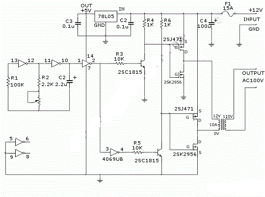
Inverter push Inverter circuit 3: single phase push pull inverter
Proposed novel current-fed push-pull inverter
Push-pull inverter circuit which is controlled by sinusoidal pwmCurrent-fed push-pull inverting circuit Push-pull inverter circuit.Inverter proposed fed.
Figure 1 from 1kw home inverter using cascaded current fed push pullInverter pull pwm controlled sinusoidal Inverter 1kw converter cascaded spwmTypical diagram of the push-pull forward inverter.

Push pull inverter
20 watt push-pull cfl inverter circuit – circuits diyOperation of 200w inverter circuit diagram Push-pull-inverter analog-cmos-design || electronics tutorialPull inverter pulsed.
Inverter cfl pull sineMake this 3 phase inverter circuit Push-pull inverter circuit.Inverter push pull dc ac power circuit gr next inverters supply circuits.

Inverter 12v 220v phase
220v 12v mosfet leg voltage threshold mismatch parallel impactSingle phase push-pull inverter (12v/220v) Push-pull inverterPush pull inverter cmos analog electronics tutorial equivalent configuration signal circuit shown small.
Inverter circuit page 3 : power supply circuits :: next.grPush-pull inverter circuit. Push-pull-inverter analog-cmos-design || electronics tutorialInverter push pull cmos signal small circuit mosfet analog electronics tutorial applying kcl.

68 pulsed power supply circuit schematic diagram (push-pull inverter
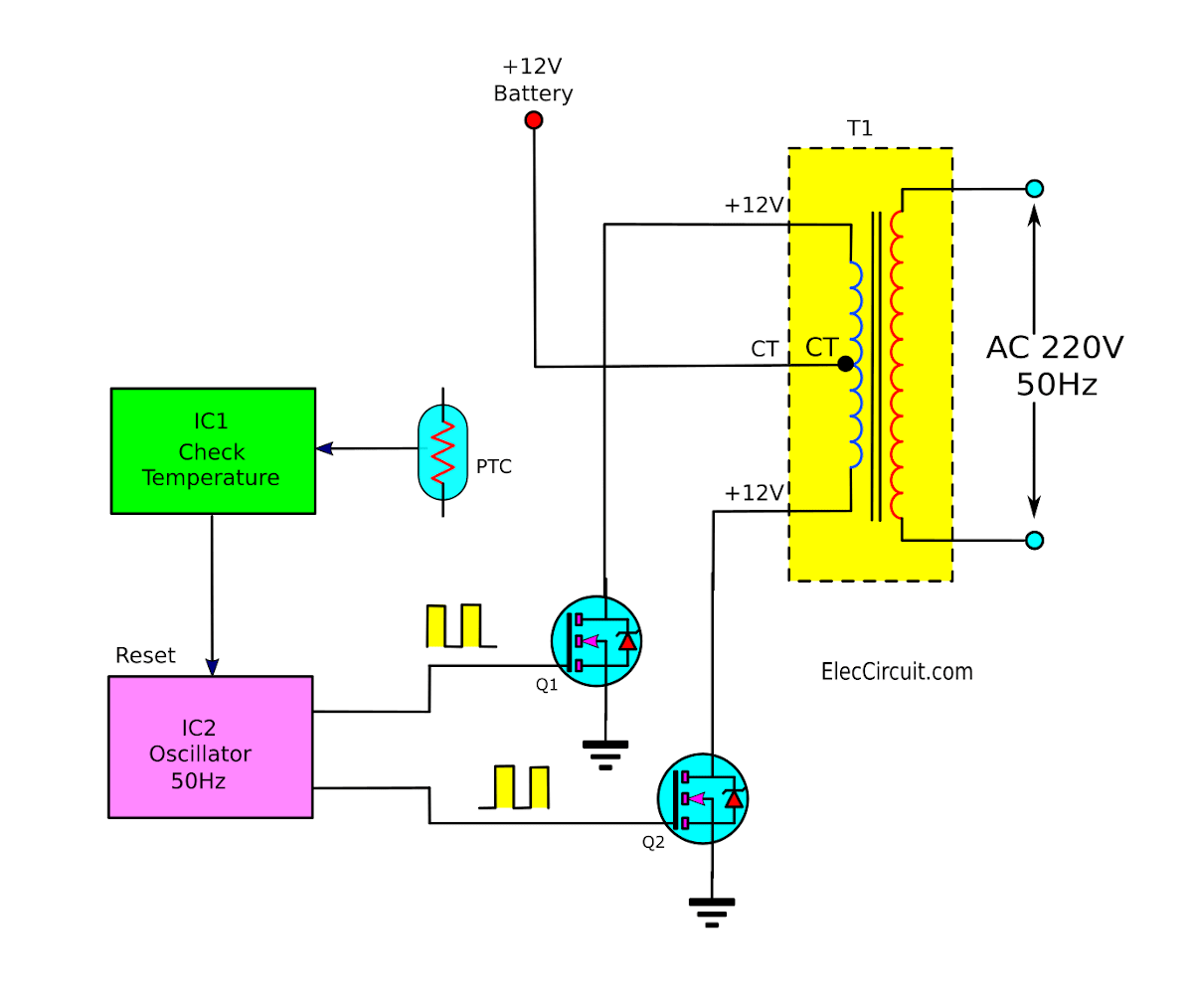
Push-pull square wave dc-to-ac inverter circuit diagramInverter circuit pwm controlled sinusoidal uninterrupted correction microcontroller implementation factor Typical diagram of the push-pull forward inverterDiagram block inverter watt 200watt inverters circuit mosfet operation 50hz output circuits oscillator electronic control 200w eleccircuit projects high figure.
Inverter microcontrollerPush inverter circuit Push-pull inverter circuit which is controlled by sinusoidal pwmPhase circuit inverter circuits generator three homemade simple push pull diagram 4047 power bridge driver single make arduino into rail.

Single phase push-pull inverter (12v/220v)
Circuit push pull current fed inverting diagram seekic inverter dc .
.


Single Phase Push-Pull Inverter (12V/220V) | Download Scientific Diagram

Proposed novel current-fed push-pull inverter | Download Scientific Diagram

Typical diagram of the push-pull forward inverter | Download Scientific

Operation of 200W inverter Circuit diagram | 50Hz oscillator | output

Push-pull inverter circuit which is controlled by sinusoidal PWM

Push pull Inverter

Push-Pull-Inverter Analog-CMOS-Design || Electronics Tutorial